


For all drawings from sketch design and municipal submission to schedules and details a title block is included on each drawing sheet containing general construction notes as per our companies and NBR regulations; a drawing title, purpose, drawing number, company details and person responsible for the specific drawing is all included in the same title block (This notation serves as a global informant to all projects following this one and won’t be mentioned again).
Furthermore please note that for each step of the drawing process (especially sketch design) many variations of the same concept are compiled in an effort to get to the desired end product. I will not include every drawing as the general concept stays the same, therefore the drawings you see are generally end products.
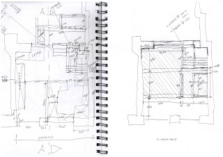
Furthermore hand sketches are included with some of the projects and serves to inform one of some specific considerations/problem solving investigations that inevitably come up as projects progress.
Project: Dasbosch Cottage, Porterville
Project Introduction:
As a start up project I had taken over the drawing up of this house from the previous student (Ryno) who had drawn up preliminary sketch designs which entailed a rectangular structure of standard masonry construction with a pitch roof and gable walls on each end (south and north elevations) of the dwelling as well as a veranda on the west end and a ‘stoep’ on the east end. The dwelling is to be built on a farm with the site being very loosely designated allowing freedom of placement in terms of weather related issues and potential physical obstructions such as hills, dams, streams, vegetation etc. View the photos at the end of the project to gain more perspective.
Sketch design

What is the purpose of this drawing/information?
A more finalised sketch design drawn up from sketches done by my Mentor (Louis Steyn) for discussion and review by the client and ourselves.
Who are the people for whom you have prepared this drawing/information?
Prepared for the architect, Client and builder for review.
Are there any other ways to provide the same drawing/information?
Yes, these drawings can still be discussed using freehand drawings and/or drawings produced by 3D drawing programmes but, having technical drawings that are to scale and dimensioned on plan and in height allows the architect to make well considered changes to the structure in terms of building reality and cost.
Explain the purpose of every component of the drawing/information mean (for example, why do you put certain dimensions on a specific drawing?)
Plan: Dimensions are provided to show wall positions and internal spaces (room sizes) so as to make accurate changes that are economic in terms of building cost and aesthetic appeal. Further dimensions are added to show for example window sizes and position as well as built in cupboards.
Sections: These dimensioned drawings provide insight into foundation types, floor levels and falls (eg. 1:100), wall heights, roofing construction and engineered structural requirements.
Elevations: These four components of the drawing provide help in determining the relationship between the plan and the different elevations as well as the visual effect of the openings in relation to the aesthetic appeal of the building as a whole as well as providing a ‘feel’ for the finished product whilst considering the physical context of the site (Light, ventilation, views and energy efficiency of the structure).
Working Drawings


What is the purpose of this drawing/information?
This drawing is specifically compiled to direct the builder in the actual construction of the dwelling. No setting out point is shown as this was discussed on site. The drawing is also used as reference by the structural engineer to calculate necessary structural reinforcements such as reinforced concrete beams (cast insitu).
Who are the people for whom you have prepared this drawing/information?
The contracted builder and structural engineer as well as building material suppliers (i.e. windows and doors).
Are there any other ways to provide the same drawing/information?
With exemption to the use of alternative drawing programmes such as Archicad, Revit, Cadi or technical hand produced drawings the format in which this information is presented is best for use and understanding by all parties involved.
Explain the purpose of every component of the drawing/information mean (for example, why do you put certain dimensions on a specific drawing?)
Plan: A scaled and dimensioned floor plan provides the builder with all the necessary information to correctly lay foundations and set out wall positions and other openings. The carpenter, plumber and various other suppliers are also able to distinguish the size (on plan), position and swing of various fittings such as windows, doors and built in cupboards. Floor finishes are also indicated.
Sections: These dimensioned drawings provide accurate information regarding structural beams ,foundation types and position as well as floor levels and falls/gradients (eg. 1:100), wall heights, roofing construction and engineered structural requirements for use by the engineer. Concise notes also provide the necessary information for the construction of foundations, floors, walls, ceiling and roofing. The sections help in clarifying any unresolved issues that can’t be addressed on plan.
Elevations: These drawings provide accurate insight into the overall finished product whilst concise notes informs the different contractors of finishes for example, cladding, paint, shutters etc. The slope of site is also more accurately portrayed.
Roof layout


What is the purpose of this drawing/information?
Whilst a professional is always employed to calculate and quantify the construction and layout of the roof structure we (the principal architectural agent to the project) always provide a proposal to the employed roofing professional to assist in the calculation of truss spans, sizes and position, especially were trusses are exposed as is the case with this specific project. The roof is after all the crown of any dwelling and should be approached accordingly.
Who are the people for whom you have prepared this drawing/information?
The roofing contractor and architect.
Are there any other ways to provide the same drawing/information?
Yes, but a technical drawing insures the best chance of correct calculation of cost and actual assembly and construction of the roof structure.
Explain the purpose of every component of the drawing/information mean (for example, why do you put certain dimensions on a specific drawing?)
Plan: Truss spacing (centre to centre) and positions, spans and proposed beam sizes are provided so that the roof structure can be correctly set out, quantified and costed. This drawing is usually accompanied by sectional elevations of the roofing structure to further assist the contractor in his/her task.
Electrical layout


What is the purpose of this drawing/information?
This diagrammatic layout of all plug points, light fittings and other points of concern overlaid onto a plan view of the structure accurately portray the position, height and type of fitting to be installed.
Who are the people for whom you have prepared this drawing/information?
Electrical engineer, architect and client.
Are there any other ways to provide the same drawing/information?
Possibly, but this means of representation of an electrical layout is well understood in the building industry and is further explained by the electrical legend accompanying the drawing.
Explain the purpose of every component of the drawing/information mean (for example, why do you put certain dimensions on a specific drawing?)
Plan: This view of the electrical layout most accurately portrays the information required by the electrical engineer to ascertain the position, height and type of fittings required in the various spaces.
Legend: This diagram further informs the parties involved as to the exact specifications of all fittings so as to clarify any unknowns.
Note: A lighting schedule may be added to assist the quantity surveyor in quantifying and costing the project (generally only required on projects of a larger scale).
Kitchen layout


What is the purpose of this drawing/information?
These drawings are done at a larger scale and serves to further assists in determining the sizes, position and types of fittings and finishes to be installed in this specific space.
Who are the people for whom you have prepared this drawing/information?
Carpenter, electrician, builder, plumber and client.
Are there any other ways to provide the same drawing/information?
No, although additional information such as colour charts (pallets), finishing materials and fitting types may be included for review by the client (this addition is more often than not compiled by interior designers and decorators depending on the scale and grandeur of the project.)
Explain the purpose of every component of the drawing/information mean (for example, why do you put certain dimensions on a specific drawing?)
Plan: Tile layout and fitting and cupboard positions are shown as well as fitting types to assist all parties involved to correctly fit and position different components to ultimately create a working and aesthetically pleasing environment for the concerned space. A diagram indicating the different internal elevations of the space is added to more easily relate the plans and elevations to one another.
Internal elevations: These drawings indicate the heights at which different components are to be installed and also include tile layouts where applicable.
Internal elevations: These drawings indicate the heights at which different components are to be installed and also include tile layouts where applicable.
Bedroom layouts


Refer to the notes on kitchen layouts as these drawings are intended for the same purpose/parties and portray the same type of information although generally excluding the plumber.
Bathroom layouts


Refer to the notes on kitchen layouts as these drawings are intended for the same purpose, parties and portray the same type of information.
Carport


What is the purpose of this drawing/information?
These drawings serve as a proposal for review and assessment pertaining to the construction, building ‘style’, used material and detailing of the structure.
Who are the people for whom you have prepared this drawing/information?
Client, architect and builder for a once of review and approval and will serve as working drawings also as this is a freestanding and very basic structure.
Are there any other ways to provide the same drawing/information?
Yes, but as this structure is in this case a very basic consideration no additional information is required (carte blanche given to building contractor)
Explain the purpose of every component of the drawing/information mean (for example, why do you put certain dimensions on a specific drawing?)
Plans: Direct builder in setting out of structure and determining column positions.
Elevations: Only east and west elevation are provided as the sections and north and south elevations are virtually the same.
Sections: These drawings give insight into the proposed roofing construction as well as the junctions were floor and wall (column) meet and were wall and roof meet.
Iron mongery: As each proposed method of construction is slightly different in it’s assembly and aesthetic appeal different bracketing systems are employed to facilitate these differences in construction assembly.
Door and window schedules


What is the purpose of this drawing/information?
To Inform the employed supplier of the exact measurements, materials and finishes required for the fenestrations.
Who are the people for whom you have prepared this drawing/information?
Builder and the supplier.
Are there any other ways to provide the same drawing/information?
Are there any other ways to provide the same drawing/information?
Yes, by means of a spreadsheet document or diagram but it would be considerably harder to decipher and understand.
Explain the purpose of every component of the drawing/information mean (for example, why do you put certain dimensions on a specific drawing?)
Title block: Included in the title block you will find the exact specifications of size, material, finish and amount required for each window type and door type as well as general specifications (A more polite way of saying terms and conditions) and like all other drawings will also contain the particulars of our company and the project at hand.
Title block: Included in the title block you will find the exact specifications of size, material, finish and amount required for each window type and door type as well as general specifications (A more polite way of saying terms and conditions) and like all other drawings will also contain the particulars of our company and the project at hand.
Elevations: As the doors and windows in this specific dwelling is of standardised materials and assembly (not of size) an elevation informing one of the height and width of each door and window type is sufficient as far as drawn information is concerned. The other notation on the drawing points out the finished floor level and the underside of each openings lintel informing the supplier of the exact height of the opening in question.
Register


What is the purpose of this drawing/information?
This document serves as a summation of all the required door and window types along with dimensions, quantities and finishes. A register of required product is sent to companies’ from sanitary ware to furnishing suppliers depending on the scale of the project.
Who are the people for whom you have prepared this drawing/information?
In this case only the supplier(s) of the fenestrations.
Are there any other ways to provide the same drawing/information?
In this case only the supplier(s) of the fenestrations.
Are there any other ways to provide the same drawing/information?
Yes, by catalogue codes if the doors and windows were of standard size. Alternatively door and windows schedules provide the same information but do not offer the luxury of a quick summation of the required product.
Explain the purpose of every component of the drawing/information mean (for example, why do you put certain dimensions on a specific drawing?)
This document type is typically set out in a tabular form with rows and columns indicating the dimensions, material type, finishes and numbers of each window and door type.
This document type is typically set out in a tabular form with rows and columns indicating the dimensions, material type, finishes and numbers of each window and door type.
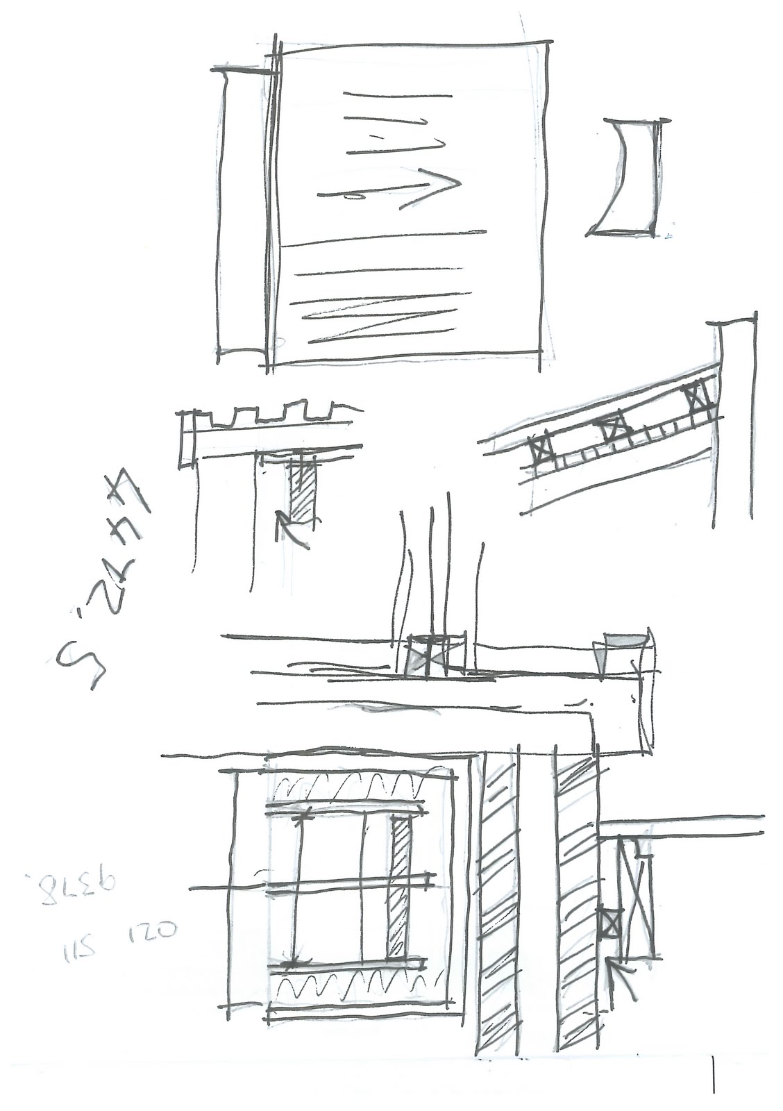
Details


What is the purpose of this drawing/information?
Were building construction varies to that of standard construction details of junctions are offered to resolve the building technique, finish and materials applied and are often drawn to a much larger scale i.e. 1:10 or 1:5. In drawings of this type a opportunity is often presented to the junior technologist to showcase his or her ability to design and problem solve.
Who are the people for whom you have prepared this drawing/information?
Building contractor
Are there any other ways to provide the same drawing/information?
No, Drawings of this type are very specific and pertain only to that singular point of concern and need therefore to be technically drawn up, scaled and dimensioned whether in 2D or 3D (many intricate details are best explained in 3D although no true scale can be attached to such a drawing)
Explain the purpose of every component of the drawing/information mean (for example, why do you put certain dimensions on a specific drawing?)
Section: The connection between column and beam is clearly illustrated to resolve the issues surrounding building construction and finish of the junction as this specific junction will be a exposed component as a finished product and the placement of different members of this component will affect the roof height of this structure and ultimately the wall and roof height of the adjoining structure.
3D’s


What is the purpose of this drawing/information?
This drawing served only as training on the programme Revit in my first week and is a representation of the dwelling at the initial stages of design. Thanks to Andrè Wiese I did manage to learn a few things.
Who are the people for whom you have prepared this drawing/information?
No critic of mine if that’s what is asked (lol). Just as practice.
Are there any other ways to provide the same drawing/information?
Yes, hand sketched drawings and even better; actual scaled, built models which provide the best insight to many design questions.
Explain the purpose of every component of the drawing/information mean (for example, why do you put certain dimensions on a specific drawing?)
To more accurately portray the proposed finished product to the client.
To more accurately portray the proposed finished product to the client.
Photos


Provided only as view to the progress of construction.
Project: SCP (Shoprite Checkers Properties), Canelands, Durban
Project: SCP (Shoprite Checkers Properties), Canelands, Durban
Project Introduction:
Our company’s biggest client and provider of steady income is SCP. We are responsible for the design, and in some cases project management, of all there DC’s (distribution centres) throughout Africa. Furthermore we are in many cases the principal agent for the design of the retail/office buildings (malls) where SCP is to be the intended anchor for a new development. As a second ‘practice run’ I was given this small guard house to draw up. Because of the scale of most projects of this type the work load is distributed between a number of technologists and sometimes architects to accommodate the rigouris programme set for the development and construction of the project. My responsibility was to draw up this guard house situated at the perimeter of the property which is intended for the scanning and control of staff traffic in and out of the property.
Sketch design


What is the purpose of this drawing/information?
This drawing serves as a design proposal for review by the client and other involved parties to determine its relevance to the project as a whole.
Who are the people for whom you have prepared this drawing/information?
I would like to say the client but as this drawing was done when I was still in training, it was prepared for the in house project leader for
review before being issued.
Are there any other ways to provide the same drawing/information?
Yes, for the purpose of these drawing types 3D model drawings (placed in context) provide much better insight when looking at the project as a whole.
Explain the purpose of every component of the drawing/information mean (for example, why do you put certain dimensions on a specific drawing?)
Elevations: As every component of the project has to be approved by a number of parties involved to determine the construction cost and
viability as well as architectural relevance, function and aesthetic appeal, this drawing serves as a design proposal showing the finished project in
elevation for review by the client.
Plan: This component of the drawing serves to inform the relevant parties of the circulation within the structure as well as pointing out access to, from and around the structure and further indicating the position of all window openings so as to assess its relevance in terms of visual control.
3D’s


What is the purpose of this drawing/information?
These two drawings served only as training on the programme Sketchup in my second week and is a representation of the structure at the initial stages of design. Unfortunately I was unable to complete the drawing as I was moved to a permanent appointed station which, at the time did not have the ability to properly and easily navigate around 3D programmes.
Who are the people for whom you have prepared this drawing/information?
No one in specific as this exercise served only as practice as previously mentioned.
Are there any other ways to provide the same drawing/information?
Yes, hand sketched drawings and even better; actual scaled, built models which provide the best insight to many design questions.
Explain the purpose of every component of the drawing/information mean (for example, why do you put certain dimensions on a specific drawing?)
To more accurately portray the proposed finished product to the client.
Project: House Houghton – Bathroom addition
Project Introduction:
House Houghton is a dwelling which was designed and built by our company (Louis Steyn) a number of years ago for a client (Mr. Houghton). The dwelling has recently been instituted as a guest house and the client requested a lightweight bathroom addition to be added on the first floor over an existing parapet enclosed ground floor extension. Although the parapet walls on which the new proposed structure will rest are load bearing, a request for a light weight wood structure was made to accommodate the clay soil on which the original structure was built. This consideration was implemented to prevent any future cracking from occurring due to potential movement caused by excess weight added to the current walls. This project, although not complete, has offered me the opportunity to explore some alternate methods of construction and entails a fair amount more research than what the drawings portray. The technology employed is that of Everite Nutec solutions and is compiled of (from exterior to interior), fibre cement cladding, SA pine timber members and treated plaster board with DPM, DPC and insulation installed where relevant.
Council Submission


Who are the people for whom you have prepared this drawing/information?
As a set of three drawings, the first was for approval by the client, the second is simply a section on a larger scale to more accurately portray
the employed technology and the third, when complete, will serve as both council submission and working drawings to the contracted builder as
the employed contractor will also be the certificate holder to the NBR approved technology that will be implemented. Furthermore, the client is
also a structural engineer who is regularly employed by our company to calculate and manage the engineering requirements on many of our
projects and will therefore not require too much assistance beyond the architectural feel and understanding of this addition to the dwelling.
Are there any other ways to provide the same drawing/information?
Not that I know of. Drawings that are issued for the express purpose of review and approval by council have to conform to certain requirements as imposed by our local and national authorities.
Explain the purpose of every component of the drawing/information mean (for example, why do you put certain dimensions on a specific drawing?)
Site plan: A scaled and dimensioned site plan provides council with all the necessary information to assess the validity of the proposed addition to the existing property.
· Full site boundaries are indicated along with street names adjacent to the property as well as a north point. This information allows council to pinpoint the exact coordinates (placement) and extent of the property.
· Building lines and setbacks are included to indicate the extent to which and were the dwelling may extend (normally 50% of full property). These building lines are not set in stone; so to speak and may be relaxed if a argument to the contrary (by application) is deemed fit by council.
· The foot print of the building is also included by means of a outline and hatch so that the proposed extension may be accessed in relation to the existing building.
· A hatched area indicating the exact size and position of the proposed extension is also included for the same reason as above.
· A drainage reticulation plan (sewer run) is included to indicate were new plumbing will be installed and how and where it will connect with the existing drainage.
Plan: A scaled and dimensioned floor plan provides council with all the necessary information to correctly determine the size (m2) and
validity of the employed construction method as well as indicating wall positions and other openings. Council is also able to distinguish the
size (on plan), position and swing of various fittings such as windows and doors. Floor finishes are also indicated.
Sections: These dimensioned drawings provide accurate information regarding fixing methods as well as floor levels and falls/gradients (i.e.
1:100), wall heights, roofing construction and engineered structural requirements if applicable. Concise notes also provide the necessary
information for the assessment of construction of foundations, floors, walls, ceiling and roofing. The sections help in clarifying any
unresolved issues that can’t be addressed on plan.
Elevations: These drawings provide accurate insight into the overall finished product whilst concise notes informs one of the different
finishes for example, cladding, paint, shutters etc.
Electrical layout: Although not required by council the electrical layout is included to make this project an easy to understand, all in one drawing.
What is the purpose of this drawing/information?
This drawing informs the relevant authorities of the intent and extent of the proposed construction and allows them to make knowledgeable decisions pertaining to the viability and safety during and after (when fully erect) construction of the proposed development. Many other considerations i.e. building setbacks, zoning (height, size and proposed use) and heritage issues pertaining to the property in question are also investigated before plans are approved.
Larger scale section

Project: Silver Valley Mall, Port Harcourt, Nigeria
Project Introduction:
This project comprises of a set of 13 drawings all of the same type and I will therefore only submit one set of questions and awnsers in explanation of said drawings. As mentioned in a previous project (SCP Canelands) our company is often appointed as the principal architectural agent for the development of retail centres (malls) were the company SCP has the larger anchor shop within the development. As this is a new project at the very beginning stages of development my responsibility is to apply certain given sets of information to a site diagram to compile a SDP (site development plan) so as to present a proposed layout of the mall in plan view only.
SDP’s (site development plans)


What is the purpose of this drawing/information?
The SDP serves mostly as a massing and layout exercise to help the parties involved to determine the viability of the project in terms of cost of construction and annual return of investment through determining the optimal ratio between line shops, anchors, circulation, parking and shop yards (product drop off).
Who are the people for whom you have prepared this drawing/information?
The client, developer, main vendors and the quantity surveyor for review and discussion.
Are there any other ways to provide the same drawing/information?
No, this information is most accurately portrayed as a plan view SDP where the wanted extents, ratios and circulation can be accurately shown in relation to the physical limitations of the actual site.
Are there any other ways to provide the same drawing/information?
No, this information is most accurately portrayed as a plan view SDP where the wanted extents, ratios and circulation can be accurately shown in relation to the physical limitations of the actual site.
Explain the purpose of every component of the drawing/information mean (for example, why do you put certain dimensions on a specific drawing?)
Note: Refer to the PDF titled OPTION 14 A2 as this is the most well developed SDP.
Grid: To more easily organise different spaces on a site of this size a 10x10m grid system is laid down first. This grid is numerically numbered in one direction and alphabetically numbered in the other direction so as to easily modulate spaces that make proportional sense [i.e. a typical line shop in a mall of this type will have 1 to 2 ratio on plan meaning length to width ratio. This configuration allows for a deep enough space to accommodate services (kitchenette), goods collection area and storage to the rear of the unit whilst minimising the expanse of the more expensive shop front which is normally made mostly of glass.]
Site boundaries and adjacent roads: These components are included to contextualise the site.
Parking: A very important consideration as parking, circulation roads and shop yards inevitably take up a large part of the site and have to conform to certain regulated sizes. The correct ratio of parking to, general letting area has to be achieved to ensure a viable and properly functioning development. Whilst stacked parking is also a consideration that needs to be taken into account, the cost of its construction in relation to the returns that will be gain from the actual mall has to make financial sense. Furthermore the construction of a stacked parkcade has to make architectural sense when seeing the building in elevation.
Colour coded areas: The structure is divided into distinct areas indicating line shops, tertiary vendors, circulation, future development and services (mall generators and water plant). All colour coded areas are labelled to show intended use and expanse (in m2).
Colour coded areas: The structure is divided into distinct areas indicating line shops, tertiary vendors, circulation, future development and services (mall generators and water plant). All colour coded areas are labelled to show intended use and expanse (in m2).
Notes: Two sets of notes are provided. The first is to indicate the expanse of the whole site as well as the portion of the site that will be developed and the portion of the site that is reserved for future development. The second set of notes serves as a summary of the different mall areas (m2) and to indicate the amount of required and available parking.
Project: House Basson, erf116, Langebaan
Project introduction:
This project involves a simple extension of the already existing dwelling. I have no real input or involvement in this project and was simply appointed the task of drawing up the base plans (before the proposed addition) from traced (scanned) drawings. Along with the base drawings also find the scanned original plans from which these drawings were traced.
Traced base plans


What is the purpose of this drawing/information?
These base plans simply make it easier for the architect (Shanne Truter) to overlay his design proposal onto that which is already existing.
Who are the people for whom you have prepared this drawing/information?
A partner in the firm, Shanne Truter.
Are there any other ways to provide the same drawing/information?
Yes, but eventually the base plans will have to be traced to be able to submit a council drawing.
Explain the purpose of every component of the drawing/information mean (for example, why do you put certain dimensions on a specific drawing?)
Plan and elevations: These drawings all serve only as a base over which the new proposed extension will be overlaid on.
Project: Saint Phillips Church
Project introduction:
An open handed and giving attitude is very important in establishing a balanced and honest life style. Louis Steyn (my mentor and architect) is of this belief and he eagerly brings his skills to the table to assist the underprivileged in gaining a sense of worth. Pro bono work such as this project is a way of giving back to the community and helps to spread the word of God. For this project a new multipurpose hall is to be added to the existing church. A previously free standing community hall had very unfortunately collapsed and therefore the need for a new one. This project has offered me the opportunity to explore steel construction in the form of portal frames with masonry infill panels. My responsibility was to draw up a council submission from hand drawn sketch designs done by the architect.
Council Submission


What is the purpose of this drawing/information?
This drawing when complete will serve as a council submission for approval by the local authorities.
Who are the people for whom you have prepared this drawing/information?
The local authority under whose jurisdiction this building falls as well as the employed engineer (also pro bono) for the calculation of steel member sizes, thickness and compound strength to accommodate truss spans, lateral forces and so on.
Are there any other ways to provide the same drawing/information?
Not that I know of. Drawings that are issued for the express purpose of review and approval by council have to conform to certain requirements as imposed by our local and national authorities.
Explain the purpose of every component of the drawing/information mean (for example, why do you put certain dimensions on a specific drawing?)
Site plan: A scaled and dimensioned site plan provides council with all the necessary information to assess the validity of the proposed addition to the existing property.
· Full site boundaries are indicated along with street names adjacent to the property as well as a north point. This information allows council to pinpoint the exact coordinates (placement) and extent of the property.
· Building lines and setbacks are included to indicate the extent to which and were the dwelling may extend (normally 50% of full property). These building lines are not set in stone and may be relaxed if a argument to the contrary (by application) is deemed fit by council.
· The foot print of the building is also included by means of a outline and hatch so that the proposed extension may be accessed in relation to the existing building.
· A hatched area indicating the exact size and position of the proposed extension is also included for the same reason as above.
· A hatched area indicating the collapsed structures foot print is also included and also helps to justify our intent to exceed the building setbacks with the new proposed extension as was the case with the previous structure.
Plan: A scaled and dimensioned floor plan provides council with all the necessary information to correctly determine the size (m2) and
validity of the employed construction method as well as indicating wall positions and other openings. Council is also able to distinguish the
size (on plan), position and swing of various fittings such as windows and doors. Floor finishes are also indicated.
Sections: These dimensioned drawings provide accurate information regarding fixing methods as well as floor levels and falls/gradients (i.e.
1:100), wall heights, roofing construction and engineered structural requirements if applicable. Concise notes also provide the necessary
information for the assessment of construction of foundations, floors, walls, ceiling and roofing. The sections help in clarifying any
unresolved issues that can’t be addressed on plan.
Elevations: These drawings provide accurate insight into the overall finished product whilst concise notes informs one of the different
finishes for example, cladding, paint, roofing finishes etc.
Note: For the approval of this building extension an additional application had to accompany the council submission requesting a relaxation
of height restrictions that apply to the zoning by laws for this area (residential). The maximum building height allowed in this zone is 9m
and we would like to surpass that by 500mm at apex of the structure. All surrounding neighbours also have to be informed of this addition
and need to give their approval.
Gallery section

Drawn to ensure correct heights, including risers and treads.
Project: Somerset College, Autism School
Project Introduction:
This project is a large development that has taken place over a number of years with new buildings added as funds become available. The plans for the Autism School building on this site are also pro bono work done by our firm. Although this structure had been drawn up by previous students (Ryno and André), my responsibility was to research and apply a different construction technology to the structure. The employed technology is called stud column walling and is to be executed by the company Imison. I offer the following as explanation to the legitimacy and actual construction methods used in this project.
Legitimacy: For every method of construction that is not deemed to be ‘standard’ construction methodology, a certificate is issued (in this case Agrement certificate 2004/310) by the relevant authorities to the company holding the patent or construction rights to that technology - recognising the viability of said construction method in accordance with the National building regulations of South Africa. To gain this approved certificate the involved institution has to submit a series of documents showing concrete proof of their research into the structural soundness, longevity and habitability (sound, heat and water insulation) of their proposed construction type.
Method of construction:
Foundations: Replacing the traditional strip foundations used in load bearing masonry construction, a raft foundation with slab thickenings under structural walls is laid down as a base on which to construct the rest of the structure. The reason for the use of a foundation with a lower load carrying ability is because of lower cost of the construction and the fact that the structure above is also of much lighter weight than traditional masonry construction.
Note: The use of raft foundations are subject to the inspection of the soil type by an engineering specialist and are restricted to a maximum of two storeys of construction.
Walls: Light weight galvanised lip channel frames are factory built to specification from measurements taken on site. The framed panels incase 100mm thick insulation (purpose cut) of either wool or compressed polyurethane and are cross braced with approved hoop iron. A fine wire mesh is then riveted to each frame and further secured by two way wall ties (min. 4/m2) and specialized mesh clips called ‘Paroc clips’. The wire mesh serves as a key to a spray on, fibre reinforced, cement plaster applied between 25-30mm thick which is then smoothed down and finished to the clients’ specification.
Roofing: Most roof construction types can be applied to (fixed onto) this construction type with the exception of concrete slabs and other very heavy material types. Light weight galvanised mild steel or pine (also light weight) truss systems are generally used for tiled or steel roof finishes and may have exposed trusses or closed off ceilings. For the most part roof construction is of traditional methodology with the exception of the fixing of the trusses to the ‘wall plate, in this case frame tops. Galvanized mild steel L-brackets are bolted to the frame and to the sides of each truss on both sides of each truss and on either end of the truss span. The alternative is to bolt hoop irons to the sides of the frame work and then wrap them around the trusses which is similar to conventional construction methods (note that for this method it is essential for trusses to be aligned with a vertical side of a frame for it to be effective.
Council submission


Note: I submit two council plots for this project. The first plot includes diagrams (as provided by Imison) to clearly show, in drawn format, the workings of the different components of this construction method. The second is a more traditional means of stating the information required by council.
What is the purpose of this drawing/information?
This is a council submission and has been approved for construction.
Who are the people for whom you have prepared this drawing/information?
The local authority under whose jurisdiction this building falls as well as the employed construction company (Imison).
Are there any other ways to provide the same drawing/information?
No. Drawings that are issued for the express purpose of review and approval by council have to conform to certain requirements as imposed by our local and national authorities.
Explain the purpose of every component of the drawing/information mean (for example, why do you put certain dimensions on a specific drawing?)
Site plan: A scaled and dimensioned site plan of the entire estate provides council with all the necessary information to assess the validity and general placement of the proposed additional building to the existing property.
· Full site boundaries are indicated along with street names adjacent to the property as well as a north point. This information allows council to pinpoint the exact coordinates (placement) and extent of the property.
· Building lines and setbacks are included to indicate the extent to which and were the structure may extend.
· A roof plan of the building is included along with a roof plan of all the existing buildings so that the proposed structure may be accessed in relation to the existing buildings.
Locality plan: This diagram is included on a larger scale than the site plan to accurately gauge the exact position and distance from
relevant boundaries as well as show the structures drainage connections to that of the drainage already in place. The reason for these two
separate plans is simply because of the large scale of the site as a whole.
Roof plan: This drawing is included to show the extent as well as fall of the different roof planes. (I see now that I did indeed not include
the direction of falls on the roof plan. Good thing we have project reflexion so as to pick up on these mistakes.
Plan: A scaled and dimensioned floor plan provides council with all the necessary information to correctly determine the size (m2) and validity of the employed construction method as well as indicating wall positions and other openings. Council is also able to distinguish the size (on plan), position and swing of various fittings such as windows and doors. Floor finishes are also indicated.
Sections: These dimensioned drawings provide accurate information regarding fixing methods as well as floor levels and falls/gradients (i.e. 1:100), wall heights, roofing construction and engineered structural requirements (if applicable). Concise notes also provide the necessary information for the assessment of construction of foundations, floors, walls, ceiling and roofing. The sections help in clarifying any unresolved issues that can’t be addressed on plan.
Elevations: These drawings provide accurate insight into the overall finished product whilst concise notes informs one of the different finishes for example, cladding, paint, roofing finishes etc.
Project: House Keyser – Reebokstrand
Project introduction:
This holiday home has been extended and revamped a number of times and the clients current request is for a small braai room addition on the first floor balcony. My responsibility here was to draw up some sketch designs from hand drawings provided by the architect and to then convert them into a municipal submission. As you will see in the hand sketches I had made, I was afforded the opportunity to make some small designing decisions, but more so to make integral decisions as to the structural compilation of the structure (this process was very exciting and helped me to better understand the forces and stresses at play when making use of reinforced concrete slabs as a roof cover. The roof slab includes a central opening with an upstand ring beam to house a pitch roof with aluminium framed glass panel gable ends to create better inflow of light as this addition essentially faces south. This specific design intervention created some interesting construction issues as our options for the placement of support columns were very limited due to the nature of the structure below. This is where I was able to employ and test my problem solving skills. Although this is a small project I am thoroughly enjoying the design and construction problems being thrown may way.
Note: I include only hand sketches and a municipal submission for now as the Autocad generated sketch designs are not of great quality or consequence.
Council submission

Sketches


Note: I include the same basis information as answers as I have for some of the previous projects. Council drawings for the purpose of approval generally have to conform to the same drawing information and therefore fairly little new insight is gained into the requirements and composition of drawings of this type. I would also like to note at this point that we (JHSLR Architects) are many times pressed for time and therefore go directly from hand sketches to municipal submissions. Working under an architect (Louis Steyn) with such a great scope and understanding of architecture as well as a few decades of experience in this field, the need for presentation beyond hand sketches is many times unnecessary and even overboard; not excluding the fact that I am still a bit slow at generating 3D sketch proposals and as a mentioned afore we are in many cases pressed for time.
What is the purpose of this drawing/information?
This is a council submission, but has not yet been submitted for approval by council.
Who are the people for whom you have prepared this drawing/information?The local authority under whose jurisdiction this building falls, but more so for the employed structural engineer as the slab thicknesses may change depending on the outcome of his(already employed) calculations.
Are there any other ways to provide the same drawing/information?
No. Drawings that are issued for the express purpose of review and approval by council have to conform to certain requirements as imposed by our local and national authorities.
Explain the purpose of every component of the drawing/information mean (for example, why do you put certain dimensions on a specific drawing?)
Site plan (including a roof plan): A scaled and dimensioned site plan of the property provides council with all the necessary information to assess the validity and exact placement of the proposed addition to the existing structure.
· Full site boundaries are indicated along with street names and any erven adjacent to the property as well as a north point. This information allows council to pinpoint the exact coordinates (placement) and extent of the property, including the proposed new addition.
· Building lines and setbacks are included to indicate the extent to which and were the structure may extend.
· A roof plan of the building is well visible on this scale and thus does not need to be shown separately.
Plan: A scaled and dimensioned floor plan provides council with all the necessary information to correctly determine the size (m2) and validity of the employed construction method as well as indicating wall positions, structural components and other openings. Council is also able to distinguish the size (on plan), position and swing of various fittings such as windows and doors. Floor finishes and other concise notes are also included to resolve any unknowns and ore information that is not self explanatory.
Sections: These dimensioned drawings provide accurate information regarding fixing methods as well as floor levels and falls/gradients (i.e. 1:100), wall heights, roofing construction and engineered structural requirements (as is applicable in this case). Concise notes also provide the necessary information for the assessment of construction of foundations, floors, walls, ceiling and roofing. The sections help in clarifying any unresolved issues that can’t be addressed on plan.
Elevations: These drawings provide accurate insight into the overall finished product whilst concise notes informs one of the different finishes for example, cladding, paint, roofing finishes etc.
Project: SCP Bellas, Luanda, Angola
Project Introduction:
This project is headed up by one of our partners, Shanne Truter, and is the drawing responsibility of Francois........ (Senior Architectural Technologist). This drawing was given to me to do in his absence as he had to be on site in the DRC (Democratic Republic of Congo) and the issue of these drawings was urgent. My responsibility was to draw up Plans and sections of three different sets of stair cases.
Palns, sections, elevations

What is the purpose of this drawing/information?

What is the purpose of this drawing/information?
This drawing is for the express purpose of calculating the different bending moments within the staircases so as to accurately gauge the position, size and quantity of the required reinforcement.
Who are the people for whom you have prepared this drawing/information?
Who are the people for whom you have prepared this drawing/information?
The employed Structural engineering firm, as these types of calculations can only be done by qualified professionals in that specific field of expertise.
Are there any other ways to provide the same drawing/information?
Are there any other ways to provide the same drawing/information?
Yes, but as previously mentioned, this way of presenting the facts is most legible for all parties involved.
Explain the purpose of every component of the drawing/information mean (for example, why do you put certain dimensions on a specific drawing?)
Note: all 9 drawings (plans and sections) are overlaid onto a grid (10x10m) that forms part of a drawing called the master plan. The grid lines pinpoint the exact location of each stair case within the building.
Ground floor plans: All walls that are integral to the construction of the staircases are shown in a hatch. The floor area directly in front of the staircase, at FFL, is shown to establish different factors in play such as; distance to nearest doorway (min 1500mm), and m2 of the landing space at the foot of the staircase (min – the width and length of the width of the staircase). All treads are drawn in, dimensioned, and numbered to assist the ‘reader’ in understanding the drawing correctly. Treads that appear above the cut line (a section plane usually taken at 1200mm from floor level) is shown in a dotted line to indicate the continuation of the staircase to the level above)
Note: Dotted lines on drawings can be very confusing when dealing with layered drawings that are compiled from drawings from different professions i.e. engineers tend to show hidden items below the level at play in dotted lines, were architectural drawings tend to show dotted lines for components that appear above the concerned level.
Handrails/balustrades are drawn in to show the necessary safety features that are required on public staircases.
A directional arrow is included to indicate the point towards which the staircase rises (the opposite would apply when drawing staircases leading down to a level below).
A block diagram indicating the amount and rise/span of the risers and treads respectively is shown to simplify the calculating process.
First floor plans: The same drawing standards and specifications that is applicable to the ground floor plans apply here. One other point to consider; were a doorway leads onto a flight stairs, the swing of the door should always fall short of the first step down unless the swing of the door is less than 900mm, in which case the landing should be a minimum of 900mm.
Sections: as with the plan view drawings each stair is numbered. The construction type is clearly shown either by means of hatching or annotation. Floor slabs and construction material is also shown.
Note: A minimum head height clearance of 2100mm must always be insured whilst maintaining a tread span of minimum 250mm and riser of maximum 200mm in height. A rule of thumb for the minimum slab thickness carrying a staircase is 150mm (measured from the lowest point of the vertical line of each riser to a point perpendicular to that of the incline at which the staircase rises.)
Project: SCP Knysna
Project introduction:
This structure was erected about 6 years ago and was inspected (routine) for any structural and aesthetic depletion. The documentation I submit, called a snag list, serves to inform all parties involved (still under legal obligation) of the different points of concern pertaining to the buildings structural soundness and aesthetic appeal. All points of concern that do not fall under the legal obligation of any previous contractor are simply brought to the attention of the client along with suggested remedies.


What is the purpose of this drawing/information?
At this point of the snagging process this documentation is simply for the purpose of informing the involved parties of the different points of
concern and also to serve as legal proof of the points of concern.
Who are the people for whom you have prepared this drawing/information?
Essentially this documentation is for all contractors who will be involved in the repairs process of the structure.
Are there any other ways to provide the same drawing/information?
Yes many, but for our purposes an annotated photo is sufficient in portraying the necessary information. Showing a revision cloud around the
exact point of concern would further assist in clarifying any unknowns.
Explain the purpose of every component of the drawing/information mean (for
example: why do you put certain dimensions on a specific drawing?)
Each page includes a title, date, parties present, terms and conditions as well as numbered and annotated photos. These documents are self
explanatory and therefore need no further explination.
Project: Tango Restaurant
Project introduction:
This restaurant is housed in a heritage protected building in the Cape Town CBD. The client approached us to draw up and submit municipal submissions for a mezzanine level installed in the building for which no municipal approval could be found. After meeting with the client on site and measuring up the concerned space (shown by means of hand drawings) I drew up ‘as built’ plans for review by the client. A number of obvious building construction irregularities was pointed out to the client and advise was given in that regard in the effort of getting the structure up to standard for approval by council.

Sketches


What is the purpose of this drawing/information?
These drawings serve to inform the client of the exact status of the structure as it is currently built.
Who are the people for whom you have prepared this drawing/information?
The client by whom we were imployed.
Are there any other ways to provide the same drawing/information?
Yes, but this is the most effective means of communicating the information at hand.
Explain the purpose of every component of the drawing/information mean (for
example: why do you put certain dimensions on a specific drawing?)
Ground floor plan (of entire building): To pinpoint the exact area of concern within the building.
Plans, sections and the partial elevation: All these drawings serve only as information for discussion and dimensions are thus only indicated were
there are specific points of concern to be discussed.
Project: Fish Eagle Cottage
Project introduction:
This relatively small cottage is a project that has helped me gain valuable insight into the process of getting a structure erected; from the tender process to the actual construction of the dwelling and has truly assisted me in understanding the greater scope of business in the architectural direction. On this project I have been more involved in decision making involving anything from structural issues to small design related inputs. I have also been offered the opportunity to deal directly with the various contractors and have been able to visit the site to inspect the progression of site works. With more responsibility; inevitably more freedom in decision making follows. Under the guiding hand of my mentor I am truly enjoying the challenges that are being thrown my way.
The structure: The architectural idea for the structure is to keep a country feel in style, construction method and finish whilst emphasizing the idea of the old Cape Dutch ‘long house’. The structure originally served as a workers cottage with a central fire hearth (‘kommeintjie’) projecting out from the eastern facade. This concept was carried through in the new design with the general idea of a long house with central ‘kommeintjie’ staying intact when looking at the overall design.
A fairly narrow and elongated rectangle serves as living, dining and entertaining area with bedrooms including en suite bathrooms placed at the far ends of the rectangle. This symmetrical design further explores and portrays the idea of the classical Cape Dutch vernacular. A open plan kitchen complete with a flute (chimney) ending in a roof light mimics what was once a fire hearth. Other additions such as a roofed veranda, timber deck, pool and combination inside/outside braai and fire place overlook a picturesque dam on the west end of the building. A small cellar is also included below the timber deck. On the west end of the dwelling two carports leading into a courtyard are included and are also arranged in symmetrical fashion. The courtyard is enclosed by a central fountain flanked by planter seats and sliding access gates to either side. To small structures serving as a storeroom and staff toilet respectively are also accessed from the courtyard.
Sketch design and 3D’s


A start was made on a 3D rendering of the proposed dwelling but was abandoned due to time constraints. I made a sketch design proposal from Auto Cad generated drawings allowing me to easily compile working drawings and saving me a fair amount of time.
What is the purpose of this drawing/information?
Our company has been commissioned for the design of a number of structures for this specific client and therefore no formal presentation was made in view of obtaining appointment to this project.
What is the purpose of this drawing/information?
Our company has been commissioned for the design of a number of structures for this specific client and therefore no formal presentation was made in view of obtaining appointment to this project.
This is a more finalised sketch design drawn up from sketches done by my Mentor (Louis Steyn) for discussion and review by the client and ourselves.
Who are the people for whom you have prepared this drawing/information?
Prepared for the architect, Client and builder for review.
Are there any other ways to provide the same drawing/information?
Yes, these drawings can still be discussed using freehand drawings and/or drawings produced by 3D drawing programmes but, having technical drawings that are to scale and dimensioned on plan and in height allows the architect to make well considered changes to the structure in terms of building reality and cost.
Explain the purpose of every component of the drawing/information mean (for example, why do you put certain dimensions on a specific drawing?)
Plan: Dimensions are provided to show wall positions and internal spaces (room sizes) so as to make accurate changes that are economic in terms of building cost and aesthetic appeal. Further dimensions are added to show for example window sizes and position as well as built in cupboards.
Sections: These dimensioned drawings provide insight into foundation types, floor levels and falls (eg. 1:100), wall heights, roofing construction and engineered structural requirements.
Elevations: These four components of the drawing provide help in determining the relationship between the plan and the different elevations as well as the visual effect of the openings in relation to the aesthetic appeal of the building as a whole as well as providing a ‘feel’ for the finished product whilst considering the physical context of the site (Light, ventilation, views and energy efficiency of the structure).
Working Drawings


What is the purpose of this drawing/information?
This drawing is specifically compiled to direct the builder in the actual construction of the dwelling. No setting out point is shown as this factor
was predetermined by the already existing shell of the old workers cottage. The drawing is also used as reference by the structural engineer to
calculate necessary structural reinforcements such as reinforced concrete beams (cast insitu).
Who are the people for whom you have prepared this drawing/information?
The contracted builder and structural engineer as well as building material suppliers (i.e. windows and doors).
Are there any other ways to provide the same drawing/information?
With exemption to the use of alternative drawing programmes such as Archicad, Revit, Cadi or technical hand produced drawings the format in
which this information is presented is best for use and understanding by all parties involved.
Explain the purpose of every component of the drawing/information mean (for example, why do you put certain dimensions on a specific
drawing?)
Plan: A scaled and dimensioned floor plan provides the builder with all the necessary information to correctly lay foundations and set out wall
positions and other openings. The carpenter, plumber and various other suppliers are also able to distinguish the size (on plan), position and
swing of various fittings such as windows, doors and built in cupboards. Floor finishes are also indicated.
Sections: These dimensioned drawings provide accurate information regarding structural beams ,foundation types and position as well as floor
levels and falls/gradients (eg. 1:100), wall heights, roofing construction and engineered structural requirements for use by the engineer. Concise
notes also provide the necessary information for the construction of foundations, floors, walls, ceiling and roofing. The sections help in clarifying
any unresolved issues that can’t be addressed on plan.
Elevations: These drawings provide accurate insight into the overall finished product whilst concise notes informs the different contractors of finishes for example, cladding, paint, shutters etc. The slope of site is also more accurately portrayed.
Roof layout


What is the purpose of this drawing/information?
Whilst a professional is always employed to calculate and quantify the construction and layout of the roof structure we (the principal architectural agent to the project) always provide a proposal to the employed roofing professional to assist in the calculation of truss spans, sizes and position, especially were trusses are exposed as is the case with this specific project. The roof is after all the crown of any dwelling and should be approached accordingly.
Whilst a professional is always employed to calculate and quantify the construction and layout of the roof structure we (the principal architectural agent to the project) always provide a proposal to the employed roofing professional to assist in the calculation of truss spans, sizes and position, especially were trusses are exposed as is the case with this specific project. The roof is after all the crown of any dwelling and should be approached accordingly.
Who are the people for whom you have prepared this drawing/information?
The roofing contractor and architect.
Are there any other ways to provide the same drawing/information?
Not really, especially with the inclusion of a 3D rendering of the finished truss. Furthermore a technical drawing insures the best chance of
correct calculation of cost and actual assembly and construction of the roof structure.
Explain the purpose of every component of the drawing/information mean (for example, why do you put certain dimensions on a specific
drawing?)
Plan: Truss spacing (centre to centre) and positions, spans and proposed beam sizes are provided so that the roof structure can be correctly set
out, quantified and costed. This drawing is usually accompanied by sectional elevations of the roofing structure to further assist the contractor in
his/her task.
Electrical layout


What is the purpose of this drawing/information?
This diagrammatic layout of all plug points, light fittings and other points of concern overlaid onto a plan view of the structure accurately
portray the position, height and type of fitting to be installed.
This diagrammatic layout of all plug points, light fittings and other points of concern overlaid onto a plan view of the structure accurately
portray the position, height and type of fitting to be installed.
Who are the people for whom you have prepared this drawing/information?
Electrical engineer, architect and client.
Are there any other ways to provide the same drawing/information?
Possibly, but this means of representation of an electrical layout is well understood in the building industry and is further explained by the
electrical legend accompanying the drawing.
Explain the purpose of every component of the drawing/information mean (for example, why do you put certain dimensions on a specific
drawing?)
Plan: This view of the electrical layout most accurately portrays the information required by the electrical engineer to ascertain the position,
height and type of fittings required in the various spaces.
Legend: This diagram further informs the parties involved as to the exact specifications of all fittings so as to clarify any unknowns.
Note: A lighting schedule may be added to assist the quantity surveyor in quantifying and costing the project (generally only required on
projects of a larger scale).
Bathroom layouts


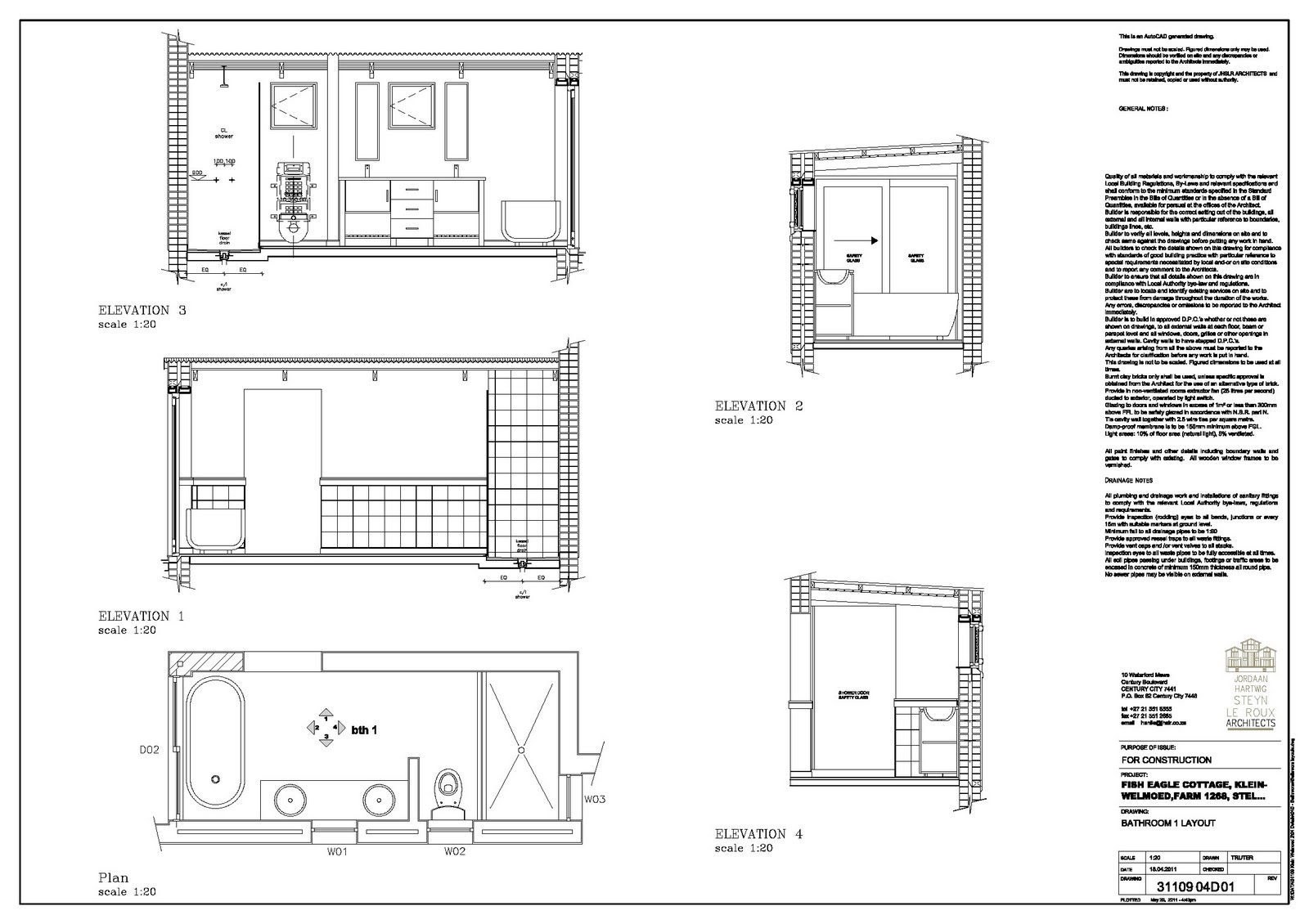


Refer to the notes on kitchen layouts as these drawings are intended for the same purpose, parties and portray the same type of information.
Door, window and gate schedules: windows
Door, window and gate schedules: windows


What is the purpose of this drawing/information?
To inform the employed supplier of the exact measurements, materials and finishes required for the fenestrations.
Who are the people for whom you have prepared this drawing/information?
Builder and the supplier.
Are there any other ways to provide the same drawing/information?
Yes, by means of a spreadsheet document or diagram but it would be considerably harder to decipher and understand.
Explain the purpose of every component of the drawing/information mean (for example, why do you put certain dimensions on a specific
drawing?)
Title block: Included in the title block you will find the exact specifications of size, material, finish and amount required for each window type
and door type as well as general specifications (A more polite way of saying terms and conditions) and like all other drawings will also contain
particulars of our company and the project at hand.
Elevations, plans and sections: As all fenestrations in this specific dwelling is custom designed and built it is therefore necessary to show each
component in elevation, section and plan. The other notation on the drawing points out the finished floor level and the underside of each
openings lintel informing the supplier of the exact height of the opening in question.
Register

What is the purpose of this drawing/information?
This document serves as a summation of all the required door, window and gate types along with dimensions, quantities and finishes. A register of required product is sent to companies’ from sanitary ware to furnishing suppliers depending on the scale of the project.
Who are the people for whom you have prepared this drawing/information?
In this case only the supplier(s) of the fenestrations.
Are there any other ways to provide the same drawing/information?
In this case only the supplier(s) of the fenestrations.
Are there any other ways to provide the same drawing/information?
Yes, by catalogue codes if the doors and windows were of standard size. Alternatively door and windows schedules provide the same information but do not offer the luxury of a quick summation of the required product.
Explain the purpose of every component of the drawing/information mean (for example, why do you put certain dimensions on a specific drawing?)
This document type is typically set out in a tabular form with rows and columns indicating the dimensions, material type, finishes and numbers of each window, door and gate type.
Iron mongery


This document type is typically set out in a tabular form with rows and columns indicating the dimensions, material type, finishes and numbers of each window, door and gate type.
Iron mongery


What is the purpose of this drawing/information?
This document serves as instruction to the employed iron monger to guide him/her in the production of specialized components required for the proper functioning and asthetics of the various gates as designed by me.
Who are the people for whom you have prepared this drawing/information?
The employed iron monger.
Are there any other ways to provide the same drawing/information?
Not if you need to be truthfull to the exact recuirements
The employed iron monger.
Are there any other ways to provide the same drawing/information?
Not if you need to be truthfull to the exact recuirements
Explain the purpose of every component of the drawing/information mean (for example, why do you put certain dimensions on a specific drawing?)
This document A Plan view and two elevations are drawn for each component, including necessary dimensions and annotations. Furthermore a annotated sectional elevation of each component (in its fixed position on the gate it relates to) is included to indicate the function (working), fixing recuirement and position of each component. The sectional elevation also shows each component in context, clearing up any uncertainties which may exist.
This document A Plan view and two elevations are drawn for each component, including necessary dimensions and annotations. Furthermore a annotated sectional elevation of each component (in its fixed position on the gate it relates to) is included to indicate the function (working), fixing recuirement and position of each component. The sectional elevation also shows each component in context, clearing up any uncertainties which may exist.
No comments:
Post a Comment